Pinball Machine
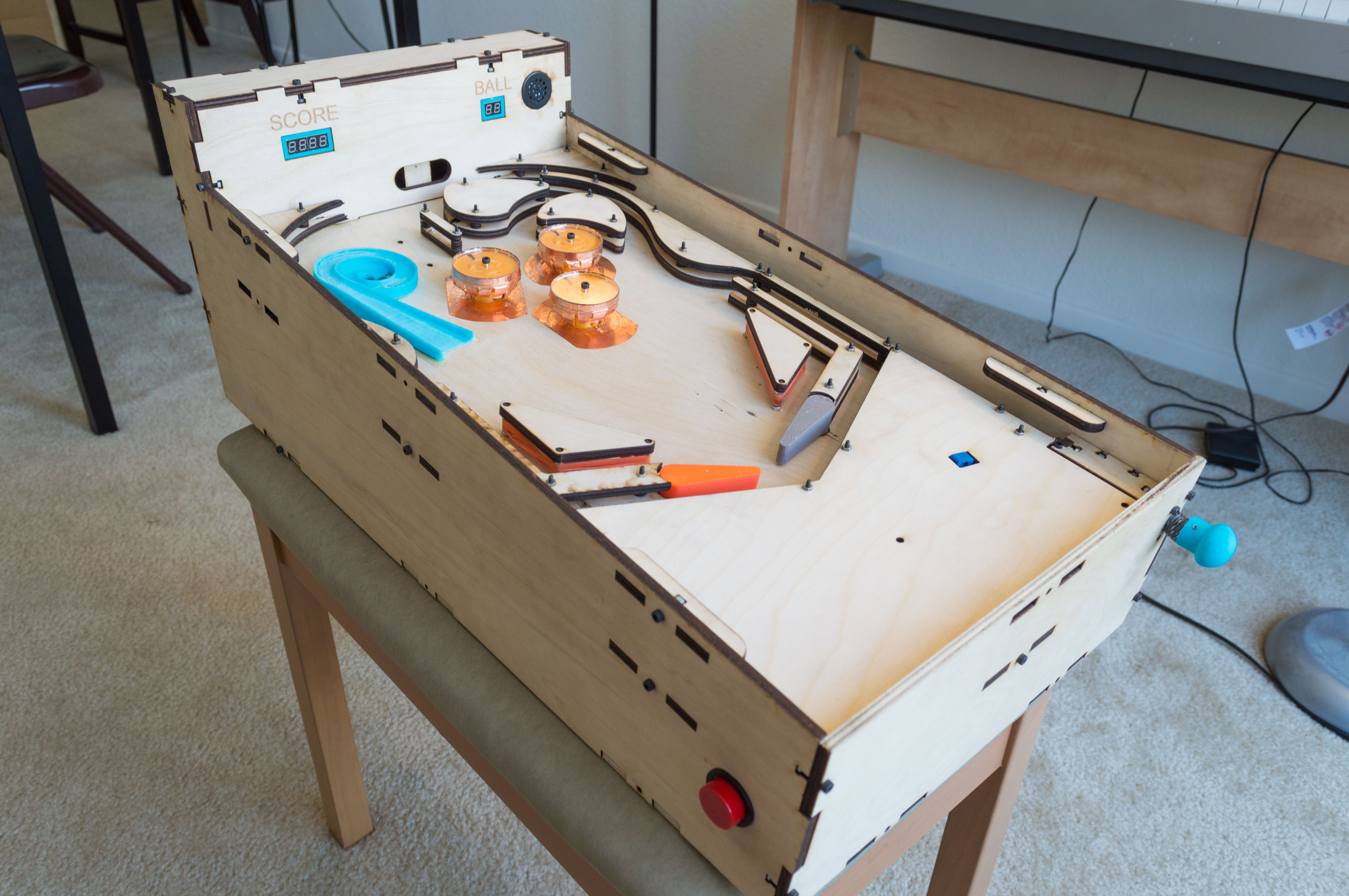
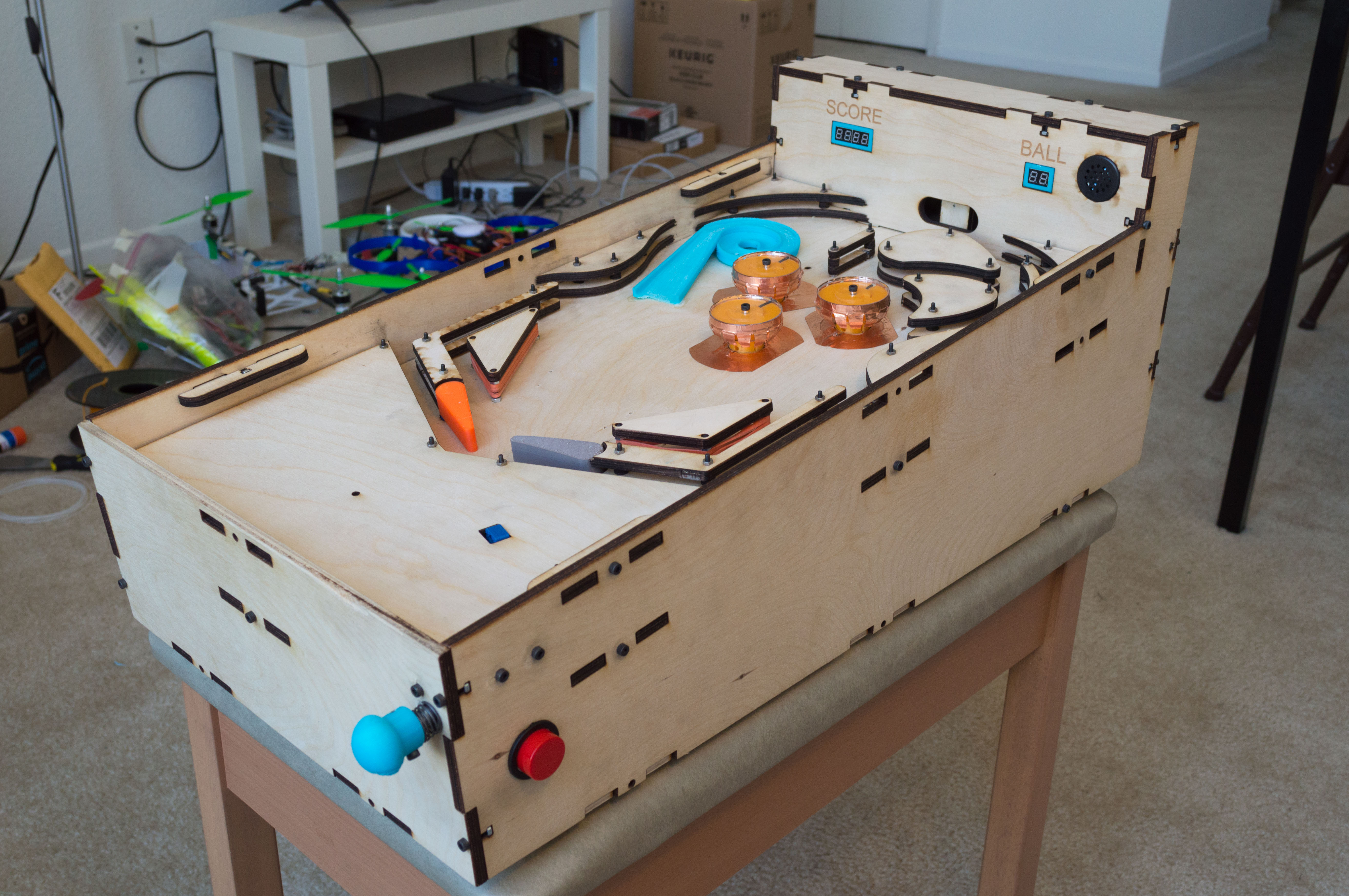
This is a pinball machine that my partner and I built for the class ECE115: Fast Prototyping. The objective of this class is to construct a full electromechanical system from scratch with 3d printed and laser cut parts.
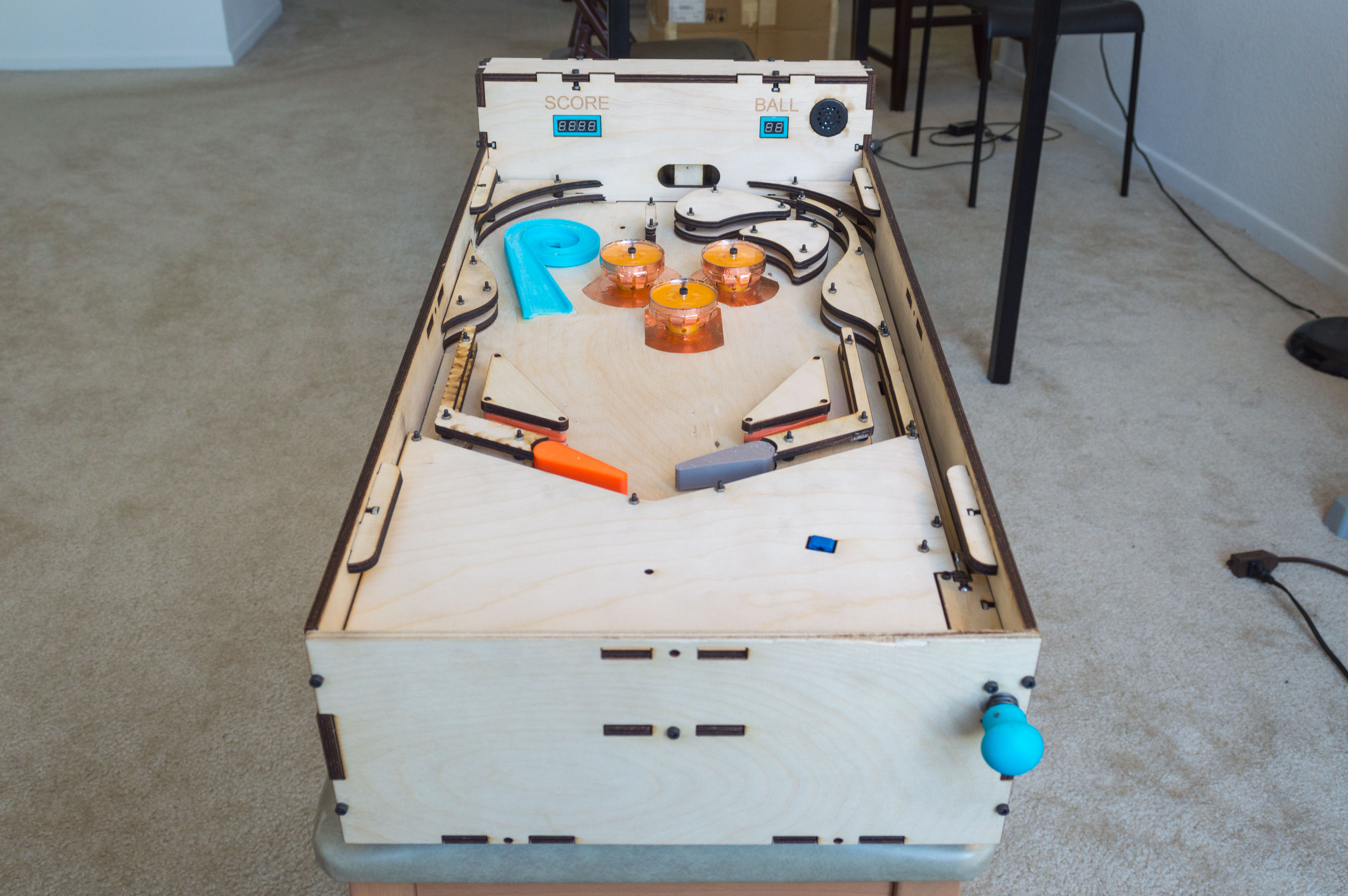
The pinball machine is controlled by an Arduino Mega and powered by a 19v laptop charger. The machine has multiple components and scoring mechanisms:
-Pop bumpers
-Flippers
-7 segment displays
-IR emitter and receivers
-Ball return servo
-Speaker
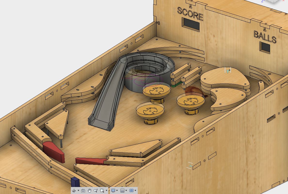
The pinball machine is constructed from quarter-inch laser-cut plywood wood and 3d printed components. The sides of the machine are fastened together with box joints and bolts. The playfield is angled at a 7 degree incline and rests on wooden brackets, which are bolted into the side walls.
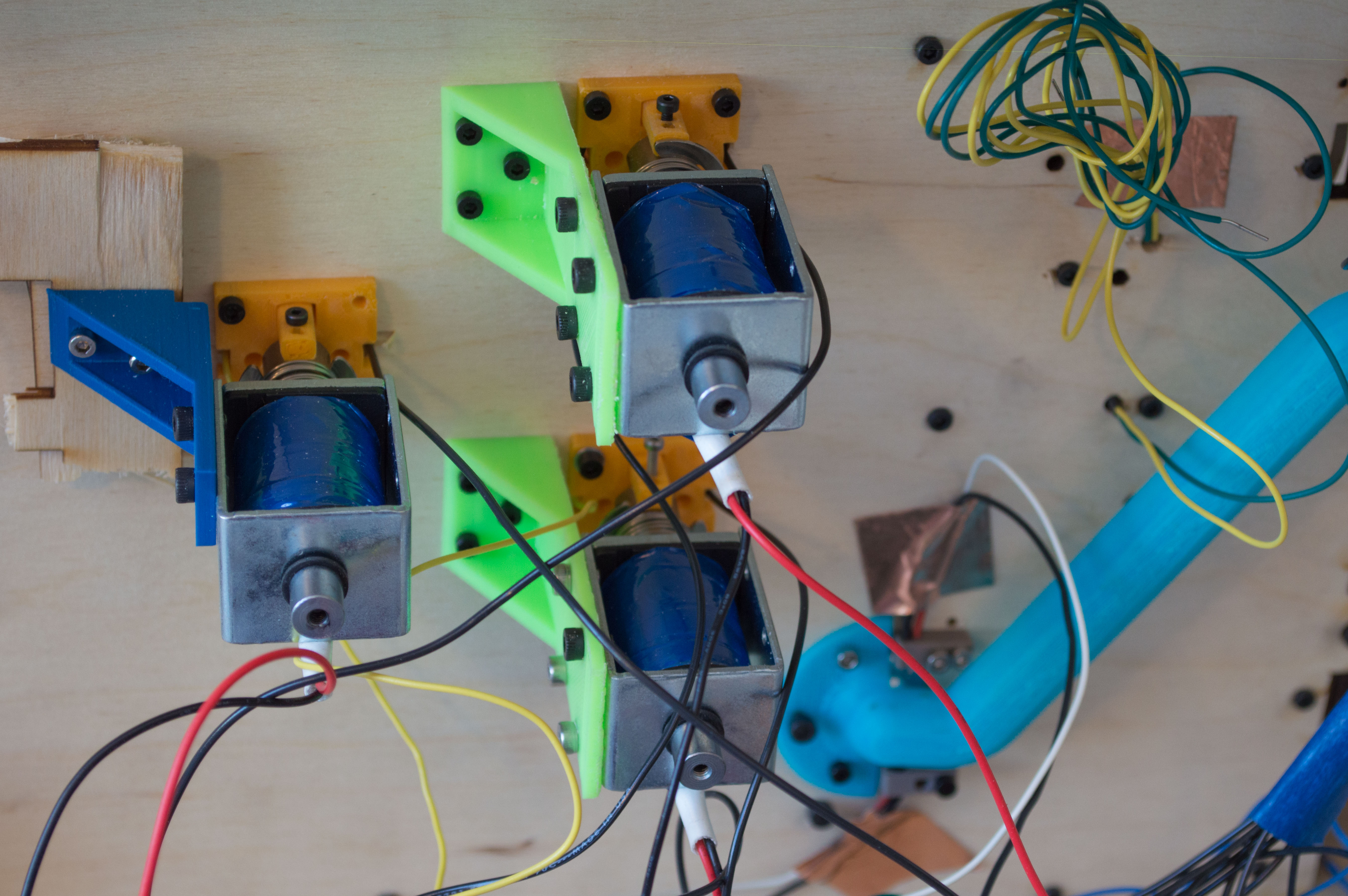
The flippers are actuated by large solenoids, which are mounted to the underside of the playfield with 3d-printed brackets. When the solenoid is activated, it pulls a tab and rotates the flipper. The flipper solenoid is controlled by buttons that are mounted on the side of the machine. The buttons are connected to 5v and the gate of a mosfet. When the button is pressed, the mosfet becomes active and powers the solenoid. The solenoid circuit is see below.
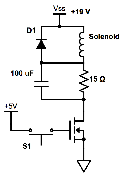
Here, the 15 ohm resistor is comprised of six 5-watt 10 ohm resistors in parallel and series configuration. The resistors were chosen so that it does not exceed the power rating when the solenoid is held active for long periods of time. A diode was placed in parallel with the solenoid to allow current to flow when the solenoid is turned off.
The capacitor was chosen such that the 19v and large inrush current is only applied momentarily to pull the solenoid down. When the solenoid is actuated, it initially pulls a large current. However, it requires less current to remain in the “Hold in” position.
When the mosfet is initially switched on, there is initially 0 volts on the capacitor, so it shorts the 10 ohm resistors. The full 19v is then applied to the solenoid. As the mosfet is held, the capacitor charges up and reduces the voltage across the solenoid. Additionally, the resistors then limit the current through the circuit.
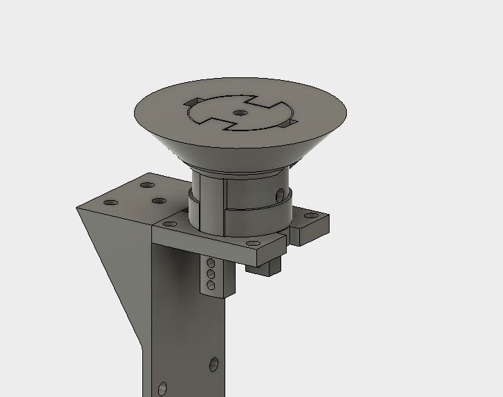
The bumpers also follow the same principle. The pillar of the bumper is encompassed by a copper-tape ring that is connected to the Arduino. The top of the cone-shaped plunger has a copper-tape curtain that hangs around the cone and is connected to 5v. When the ball rolls into the bumper, the ball completes the contact between the 5v copper tape curtain and the ring, sending 5v to the Arduino pin. The Arduino reads this switch connection and momentarily biases the mosfet gate of the solenoid driver circuit. This pulls the bumper cone down and pushes the ball away.
The spiral is comprised of two main parts - the ramp and the return mechanism. The ramp is a 3d-printed spiral that the player must propel the ball into. At the end of the spiral, the ball drops into a hole underneath the playfield and triggers an IR sensor. The ball rolls down a tunnel and into the lift mechanism. The lift mechanism is a wooden bar connected to a servo. The servo spins from 0 to ~180 degrees to lift the ball upwards and return it to the playfield.
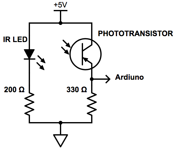
Two pairs of IR transmitter/receivers are placed on the pinball machine - at the tunnel of spiral ramp and at the ball return losing channel. The IR transmitter and receiver are housed in 3d-printed enclosures that are bolted into the playfield. The transmitter and receiver are placed such that they face each other. When the ball rolls past, it breaks the signal, which is then registered as a digital low by the Arduino. These two components are powered by 5v and have current limiting resistors. The signals are used to count the number of rounds lost and to activate the ramp servo.
The score and ball counter is depicted using six 7-segment displays. Four digits are used for the score, while two are used for the remaining ball counter. The 7-segment displays are powered by 5v and controlled via the Arduino. PNP BJT are used to facilitate a persistence of vision effect in which only one display is active at any given time, but the displays are cycled quickly so that they all appear active. The electrical schematic for two of the digits is seen in Fig 13. The displays are placed in a 3d-printed bracket and screwed onto the backboard.
The pinball machine is powered by a 19v laptop charger. The charger was connected to a barrel jack, which wired 19v to the solenoids. The 19v was also fed through a series of voltage regulators - 12v, 9v, and 5v. The 19v and 15v regulators were not used because they somehow limited the output voltage of the 5v regulator when it was fully loaded. This might have been due to the internal resistance of the components. The 5v is fed to the switches, 7 segment, IR, and Arduino. The servo was powered directly off the Arduino because it created interference when it was connected to the 5v rail.